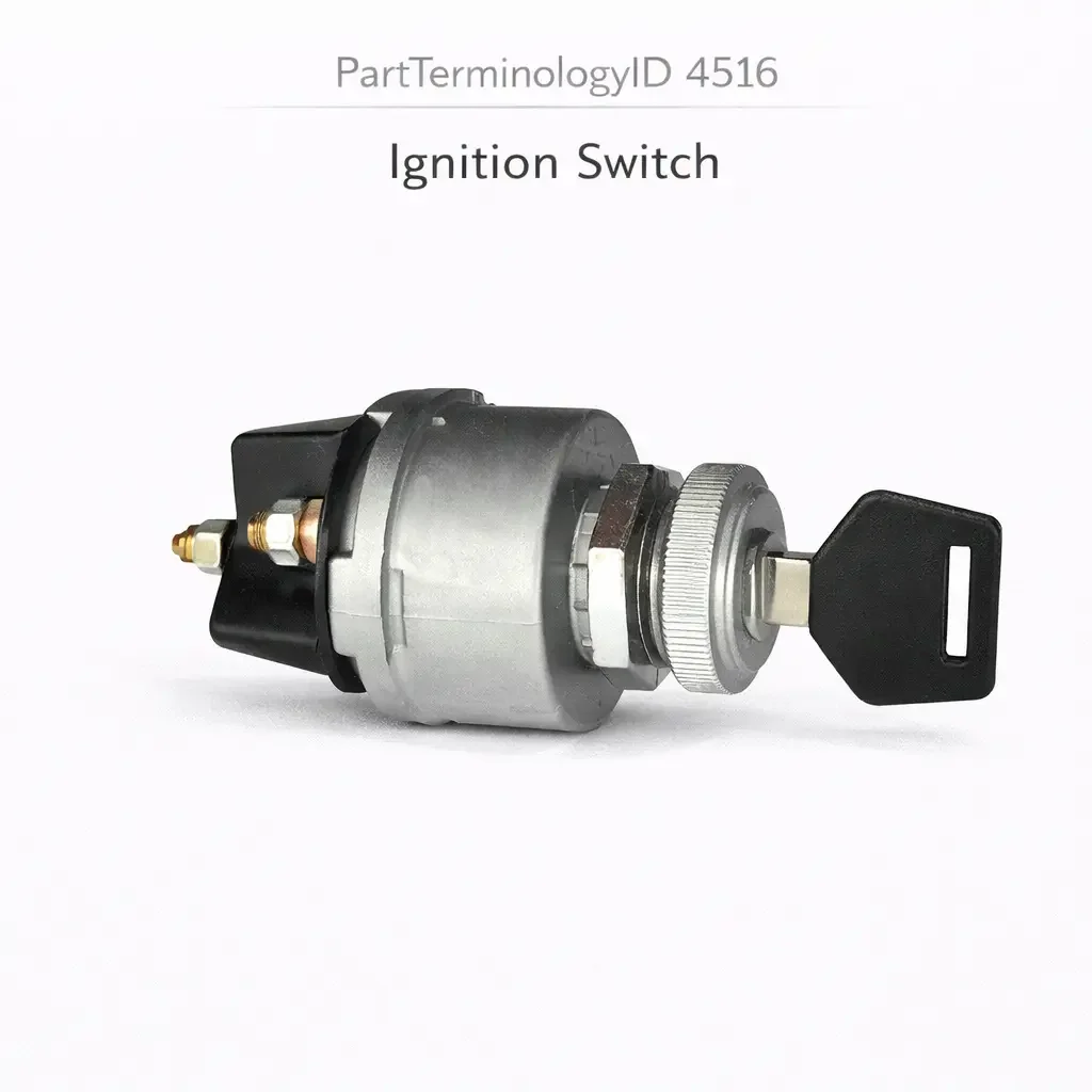
Ignition Switch (PartTerminologyID 4516): Circuit Position Coverage, Contact Current Rating, and Steering Column Interface Compatibility
Written by Arthur Simitian | PartsAdvisory
PartTerminologyID 4516, Ignition Switch, is the electrical switch module mounted in or adjacent to the steering column that carries the vehicle's ignition circuit contacts, providing discrete electrical connections for each key position (off, accessory, run, and start) that govern which vehicle systems receive power at each stage of the ignition sequence, and in many applications including additional positions for retained accessory power, bulb check, park interlock, or anti-theft system signal outputs, distinguished from PartTerminologyID 4512 (Ignition Lock Cylinder and Switch) by covering only the electrical switch module without the mechanical lock cylinder, and from PartTerminologyID 4508 (Ignition Switch Kit) by covering the standalone electrical switch component rather than a packaged multi-component kit, making it the appropriate replacement when the electrical switch contacts have failed but the mechanical lock cylinder is undamaged and operationally intact. That definition covers the standalone electrical switch replacement function correctly and leaves unresolved every question that determines whether the replacement switch module covers all active circuit positions in the original including retained accessory power, whether the contact current rating at each position matches the load presented by the circuits active at that position, whether the connector pin count and terminal assignment match the vehicle harness at the steering column mounting position, whether the switch module mounting geometry matches the steering column housing interface including the actuating cam or link that transfers lock cylinder rotation to switch actuation, whether the switch is compatible with the PASSLOCK, PASSKEY, or other anti-theft system's signal output circuit that the original switch provided through a dedicated pin, whether the replacement is compatible with the specific steering column generation including tilt, non-tilt, and telescoping column variants, and whether the replacement's run position contacts can sustain the continuous current load of all ignition-on circuits across the full operating temperature range of the column mounting environment.
It does not specify the position coverage, contact current ratings by position, connector pin count, actuating cam compatibility, anti-theft signal output, column type compatibility, or run position sustained current capacity. A listing under PartTerminologyID 4516 that states only year, make, and model without position coverage and contact current ratings cannot be evaluated by a technician replacing a failed ignition switch on a diesel truck where the run position contacts carry the ignition primary, glow plug controller, fuel pump relay, ECU supply, and engine management system simultaneously drawing 22 amperes total, and the replacement module's run position contacts are rated for 15 amperes continuous, producing contact overheating and progressive resistance increase that appears as intermittent electrical shutdowns during extended highway driving before the contacts fail completely and the engine shuts off at highway speed.
For sellers, PartTerminologyID 4516 is the most precisely scoped ignition system PartTerminologyID in the series because it covers exclusively the electrical switch module, making the electrical circuit specifications (position coverage, contact current ratings, and connector pin count) the primary attributes rather than the key compatibility and anti-theft attributes that dominate PartTerminologyIDs 4508 and 4512. The buyer arriving at PartTerminologyID 4516 has specifically identified the electrical switch module as the failed component after confirming the lock cylinder operates correctly, and requires an electrical match rather than a complete ignition system replacement.
What the Ignition Switch Does
Circuit Position Architecture and the Power Distribution Function
The ignition switch module is the central power distribution component for every electrical system in the vehicle that is governed by the ignition key position. At the off position, all ignition-controlled circuits are de-energized. At the accessory position, the radio, navigation, interior fans, and other accessories are powered while the engine management systems remain off. At the run position, the ignition primary circuit, fuel pump relay, ECU power supply, engine management systems, and safety systems are all energized for normal engine operation. At the start position, the starter motor solenoid engagement circuit is energized simultaneously with the run circuits, and some accessories (such as the blower motor and rear defroster on some applications) are briefly de-energized to reduce electrical load during cranking.
The precise set of circuits active at each position is vehicle-specific and is defined in the vehicle's wiring diagram under the ignition switch circuit map. The replacement switch must activate the same set of circuits at each position as the original. A switch that de-energizes the fuel pump relay at the start position when the original kept it active will produce a brief fuel starvation during cranking that may prevent the engine from starting on the first crank attempt. A switch that keeps the blower motor active at the start position when the original de-energized it will draw excess current during cranking, reducing the voltage available to the starter motor and extending crank duration.
Contact Current Rating by Position and the Thermal Consequence of Under-Rating
Each ignition switch position carries a different aggregate current load from the circuits that are active at that position. The accessory position typically carries the lightest load (radio, interior fans, and similar low-current accessories). The run position carries the heaviest sustained load because all engine management, ignition primary, fuel pump, and safety system circuits are simultaneously active. The start position carries the starter solenoid engagement circuit in addition to the run circuits, but this load is brief (typically 1 to 3 seconds per start event).
The contact current rating at each position is the maximum continuous current the contact can carry without generating excessive heat at the contact surface. When the contact carries current above its rating, the contact resistance (always present at a finite but small level in any metal-to-metal contact) generates heat proportional to the square of the current above the rating. Contact overheating produces three progressive failure modes. The first is increased contact resistance from contact surface oxidation accelerated by elevated temperature, which manifests as a voltage drop across the switch contact that reduces the effective voltage at all circuits in the run position. The second is softening and deformation of the contact spring that maintains contact force, reducing contact force and further increasing contact resistance in a self-reinforcing cycle. The third is contact welding from sustained high-temperature arcing at the contact surface, which leaves the switch contact permanently closed at the run position and the engine unable to be shut off by the ignition key.
The run position contact current rating must be verified against the total current draw of all run-position circuits for the specific vehicle. Diesel engines, commercial vehicles, and vehicles with high-output audio, heated seats, and multiple electronic control modules draw significantly more run-position current than a base-trim passenger car. A universal replacement switch rated for 15 amperes run position current is adequate for many passenger car applications but inadequate for a diesel commercial vehicle drawing 22 amperes at run position.
Retained Accessory Power Circuit and the Post-Key-Off Function
The retained accessory power (RAP) circuit keeps selected accessories (radio, power windows, moonroof, and in some applications the heated seats and steering wheel) powered for a defined period after the key is returned to the off position. The RAP function allows the driver and passengers to continue using these accessories during the exit process without requiring the ignition key to remain in the switch.
The RAP function is implemented in the ignition switch through one of two methods. The first is a dedicated RAP switch position between the run and off positions where the switch contacts connect the accessory circuits to power but the engine management circuits are de-energized. As the key is rotated from run toward off, it passes through this RAP position and holds the accessory circuits active until the key completes its travel to the off position, at which point a timer circuit in the BCM or a RAP relay maintains the accessory power for the defined interval before cutting it off.
The second method is a dedicated RAP output pin on the ignition switch connector that provides a sustained ground or voltage signal to the BCM's RAP input when the key is in or near the off position. The BCM uses this signal to activate its own RAP relay output for the defined interval. In this method, the RAP function depends entirely on the ignition switch providing the correct RAP signal at the correct circuit pin, and a replacement switch without this pin leaves the BCM without the RAP trigger signal, cutting off accessory power immediately when the key reaches off.
A vehicle where the radio, power windows, and moonroof stop working the moment the key is returned to off was almost certainly equipped with a RAP function in the original switch that is absent in the replacement. The listing must state whether the RAP circuit is included and must identify the pin position of the RAP output for the technician to verify continuity at the BCM's RAP input.
PASSLOCK Anti-Theft Signal Output and the Switch Module's Role
On GM vehicles with PASSLOCK systems, the ignition switch module includes a dedicated pin that carries the PASSLOCK authentication signal from the lock cylinder's resistor sensor to the BCM. The PASSLOCK sensor in the lock cylinder produces a specific resistance value when the correct key is rotated through the lock cylinder mechanism, and this resistance is transmitted through a dedicated circuit in the ignition switch connector to the BCM. The BCM compares the received resistance to its stored calibration value and enables fuel injection only if the values match.
The PASSLOCK signal pin is a low-current signal circuit (milliamp level) that passes through the ignition switch module's connector without being switched by the switch contacts themselves. The pin is always connected (regardless of key position) because the PASSLOCK authentication must be available throughout the key rotation sequence, not only at a specific switch position. A replacement switch module that does not include the PASSLOCK signal pin leaves the BCM's PASSLOCK input permanently open, which the BCM interprets as a theft attempt or sensor failure and activates the fuel disable condition, preventing engine starting indefinitely or until the BCM undergoes a PASSLOCK relearn with the lock cylinder.
The PASSLOCK signal pin must be identified in the connector diagram and its presence confirmed in every replacement ignition switch listed for PASSLOCK-equipped GM vehicles. The absence of this pin from the replacement connector produces a no-start condition on the first drive after installation, which is the most severe and most immediately actionable failure mode in the ignition switch category.
Bulb Check Circuit and the Pre-Start Warning Lamp Illumination Function
Some older domestic vehicles include a bulb check position in the ignition switch where all warning lamps in the instrument cluster are briefly illuminated as the key is inserted and rotated past the first detent, before reaching the accessory position. This bulb check illumination allows the driver to verify that all warning lamp bulbs are functional before the engine is started, because a burned-out warning lamp cannot alert the driver to a system fault during operation.
The bulb check position is a brief momentary contact between the off position and the accessory position, lasting only a fraction of a second during normal key rotation. A replacement switch without the bulb check position will not illuminate the warning lamps during key insertion, which fails the inspection on vehicles where the bulb check function is a required pre-start safety verification. The bulb check position is most commonly found on domestic vehicles from the 1970s through the early 1990s and is generally absent on modern applications.
Park Accessory Position and the Transmission Interlock Integration
Some applications include a park accessory position that activates certain accessories (typically the radio and interior fans) when the transmission selector is in the park position with the ignition key in a specific position between off and accessory. This position is used in drive-in movie theater configurations where the driver wants accessory power without starting the engine, and is mechanically interlocked with the transmission selector to prevent accessory activation in any gear other than park.
A replacement switch without the park accessory position on an application that includes it removes the driver's ability to use accessories in the traditional park accessory configuration. The park interlock mechanism in the switch housing must also match the column's transmission interlock linkage geometry for the park accessory function to engage and disengage correctly at the transmission selector's park position.
Actuating Cam and Link Geometry and the Lock Cylinder Mechanical Interface
How the lock cylinder rotation reaches the switch contacts
The ignition switch module receives its mechanical actuation from the lock cylinder through a connecting link, cam, or push rod that translates the lock cylinder's rotational input into the linear or pivoting motion that moves the switch contact wafer between positions. The geometry of this connecting mechanism is specific to the switch module design and to the steering column housing that positions the switch relative to the lock cylinder.
A replacement switch module with a different actuating cam geometry than the original will not align correctly with the lock cylinder's output shaft or connecting rod, producing one of two failure modes. If the cam is too short or positioned too close to the lock cylinder output, the switch will not reach the start position when the lock cylinder is rotated to start, leaving the engine unable to crank regardless of lock cylinder function. If the cam is too long or positioned too far from the lock cylinder output, the switch may over-travel and bypass the run position, transitioning directly from accessory to a position beyond run when the key is rotated.
The actuating cam geometry is column-generation-specific and must be confirmed from the original switch's dimensions or from the vehicle service manual's column assembly diagram. This specification is not typically listed in general catalog descriptions and must be derived from the part number cross-reference to the original equipment specification.
Tilt column versus non-tilt column switch positioning
Tilt and non-tilt steering columns position the ignition switch module at different distances from the steering wheel and at different angular orientations relative to the column centerline. The switch module mounting bracket or housing must match the column's switch mounting boss geometry for the module to seat correctly and for the actuating link to align with the lock cylinder output.
Tilt columns add a pivot mechanism to the column that allows the upper section to be positioned at different angles relative to the driver. The ignition switch module in a tilt column must be positioned to maintain correct actuating link geometry across the full range of tilt positions. A switch module designed for a fixed non-tilt column position may produce actuating link interference or insufficient link engagement at specific tilt positions, producing position-dependent ignition switch performance where the switch works correctly at one tilt position but fails to reach the start position at another.
The column type must be confirmed before ordering a replacement ignition switch module, following the same convention established for PartTerminologyIDs 4508 and 4512.
Why This Part Generates Returns
Buyers return ignition switch modules because the run position contact rating is 15 amperes and the diesel vehicle's run position circuits draw 22 amperes, producing contact overheating that manifests as intermittent electrical shutdowns during extended highway driving before complete contact failure; the retained accessory power pin is absent and the radio, power windows, and moonroof cut off immediately at key removal where the original switch maintained them for 10 minutes; the PASSLOCK signal pin is absent and the BCM's PASSLOCK input is open, activating the fuel disable condition and preventing the engine from starting after the first ignition cycle with the new switch; the connector is a seven-pin type and the harness at the column position has nine pins because the original switch included the bulb check ground output and the park accessory position contacts that the replacement omits; the actuating cam geometry is 3mm shorter than the original and the switch cannot reach the start position when the lock cylinder is rotated to start, leaving the engine unable to crank despite a correctly functioning lock cylinder; the replacement is specified for a non-tilt column and the vehicle has a tilt column where the switch mounting boss is positioned 8mm further from the lock cylinder output shaft; the start position contact is rated for the same current as the run position but the vehicle has an electric motor-driven power steering pump that draws an additional 8 amperes during the start crank event, exceeding the start contact rating and arcing at contact closure on every cold start; and the replacement does not include the start position circuit de-energization of the blower motor present in the original, causing the blower motor to remain energized during cranking and reducing starter motor voltage below the threshold for reliable cold-start engagement on below-freezing mornings.
Top Return Scenarios
Scenario 1: "Run contact rated 15 amperes, diesel run circuits draw 22 amperes, intermittent shutdown at highway speed"
The buyer installs the replacement ignition switch on a diesel commercial vehicle. Electrical function is normal on short urban drives. During a 3-hour highway trip, the instrument cluster and engine management systems briefly lose power for a fraction of a second at intervals that become more frequent as the drive progresses. On the fourth occurrence, the engine shuts off at 65 mph. The run position contacts are operating at 147 percent of their rated current, producing progressive contact surface heating that increases contact resistance and eventually causes the contact to open momentarily under the thermal stress of sustained elevated current.
Prevention language: "Run position contact current rating: [X] amperes continuous. Verify the total current draw of all run-position circuits including ignition primary, fuel pump relay, ECU supply, engine management modules, and any additional systems active at run. Diesel engines and commercial vehicles carry significantly higher run-position loads than equivalent gasoline passenger cars. An undersized run contact rating produces intermittent electrical shutdowns that worsen with extended operation before complete contact failure."
Scenario 2: "RAP pin absent, radio and power windows cut off immediately at key removal"
The buyer installs the replacement switch. All ignition positions function correctly. The radio, power windows, and moonroof cut off immediately when the key is returned to off. The original switch provided a RAP signal through a dedicated pin to the BCM, which maintained these accessories for 10 minutes after key-off. The replacement's connector does not include the RAP output pin.
Prevention language: "Retained accessory power (RAP) output: [included at pin [X] / not included]. The RAP output pin provides the BCM with the signal to maintain accessory power after key-off. A replacement without this pin removes the BCM's RAP trigger, cutting off radio, power windows, and moonroof immediately at key removal. Verify RAP pin inclusion and position against the original switch connector."
Scenario 3: "PASSLOCK signal pin absent, BCM fuel disable active, no-start after first ignition cycle"
The buyer installs the replacement switch on a GM PASSLOCK-equipped vehicle. The lock cylinder and all electrical ignition positions work correctly on the first start. After the vehicle is driven and the ignition is cycled off and on again, the engine cranks but does not start. The BCM received a correct PASSLOCK signal on the first start because the original switch was still providing residual circuit contact during the replacement process. After the replacement switch is fully seated, the BCM's PASSLOCK input is permanently open because the replacement connector lacks the PASSLOCK signal pin. The BCM activates the fuel disable condition.
Prevention language: "PASSLOCK signal output pin: [included at pin [X], carries PASSLOCK sensor signal from lock cylinder to BCM / not included]. PASSLOCK vehicles require the ignition switch to route the lock cylinder's resistance sensor signal to the BCM through a dedicated low-current pin. A replacement without this pin leaves the BCM PASSLOCK input permanently open, activating the fuel disable condition on the second ignition cycle."
Scenario 4: "Actuating cam 3mm shorter than original, switch cannot reach start position, engine will not crank"
The buyer installs the replacement switch module. The accessory and run positions work correctly. When the key is rotated to the start position, the engine does not crank. The switch module's actuating cam is 3mm shorter than the original, and at the lock cylinder's full start rotation, the cam moves the switch contact only to the run position rather than the start position. The starter solenoid circuit never receives the start signal.
Prevention language: "Actuating cam length: [X] mm. Verify the actuating cam geometry against the original switch and the lock cylinder's output shaft travel at the start position. A cam 3mm shorter than the original will position the switch contact at the run position rather than the start position at full key rotation, preventing starter engagement without any visible installation error."
Scenario 5: "Non-tilt switch module in tilt column, mounting boss 8mm offset, actuating link misalignment at mid-tilt position"
The buyer installs the non-tilt replacement switch module on a tilt column vehicle. At the lowest tilt position (steering wheel down), the actuating link is slightly short of full engagement with the switch module. At the neutral tilt position, function is correct. At the highest tilt position, the actuating link over-travels and the switch bypasses the run position when the key is rotated from accessory to run. The engine cannot be maintained in the run position at maximum tilt.
Prevention language: "Steering column type: [tilt / non-tilt / telescoping]. This switch module is specified for [column type]. Tilt column switch modules maintain correct actuating link geometry across the full tilt range. A non-tilt switch module installed in a tilt column will produce position-dependent function where the switch works correctly at one tilt position but fails to reach or maintain positions at other tilt settings."
Scenario 6: "Seven-pin replacement in nine-pin harness, bulb check and park accessory circuits unconnected"
The buyer installs the replacement switch on an older domestic vehicle. All four main ignition positions function correctly. The instrument cluster warning lamps no longer illuminate briefly on key insertion (bulb check absent). The park accessory function does not activate when the transmission is in park and the key is in the accessory-adjacent position. The replacement's seven-pin connector does not include the bulb check ground output or the park accessory position contact present in the original nine-pin connector.
Prevention language: "Connector pin count: [X] pins covering [off, accessory, run, start, RAP, bulb check ground, park accessory, PASSLOCK signal, and ground as applicable]. Verify pin count and function mapping against the original harness connector. A replacement with fewer pins than the original leaves active circuit functions permanently unconnected. Bulb check and park accessory functions are not covered in base replacement switches on some applications."
Scenario 7: "Start contact arc on cold-start with power steering pump load, progressive pitting within 200 starts"
The buyer installs the replacement switch on a vehicle with an electric motor-driven power steering pump (EMPS) that draws 8 amperes on startup. The start position contact is rated for 12 amperes. The run-position circuits draw 10 amperes simultaneously with the EMPS at start, producing a total of 18 amperes through the start contact. Each start event closes the contact under 18 amperes (50 percent above its 12-ampere rating) and opens it when the key is released to run. The arc at opening under 18 amperes produces pitting that accumulates progressively. After 200 cold-start events the start contact has pitted to the point of intermittent engagement.
Prevention language: "Start position contact current rating: [X] amperes. Verify the total current at start position including run-position circuits that remain active during cranking and any additional loads that are energized only at start (electric power steering pump, heated windshield, or other start-specific loads). An undersized start contact produces arc pitting that accumulates over start events and produces intermittent starting before complete contact failure."
Scenario 8: "Blower motor not de-energized at start, reduced cranking voltage, hard start on cold mornings"
The original ignition switch de-energized the blower motor circuit at the start position to reduce electrical load during cranking. The replacement switch keeps the blower motor energized at start. The blower motor draws 8 amperes during operation. At cold ambient temperatures, the additional 8-ampere blower load reduces the battery voltage available to the starter motor by approximately 0.4 volts. On mornings below minus 10 degrees Celsius where battery capacity is already reduced, the 0.4-volt reduction in starter motor voltage is sufficient to prevent the starter from reaching the minimum speed for reliable combustion initiation on the first crank attempt.
Prevention language: "Start position circuit de-energization: circuits de-energized at start position on original switch: [list circuits]. Verify the start position circuit map against the original switch. Circuits that should be de-energized during cranking to reduce electrical load must be confirmed as de-energized in the replacement. Maintaining high-current accessory loads during cranking reduces starter motor voltage and increases crank duration, which is most consequential at cold ambient temperatures."
Core Listing Attributes for PartTerminologyID 4516
PartTerminologyID: 4516
Component: Ignition Switch (electrical switch module only, no lock cylinder)
Circuit position coverage: list all positions (off, accessory, run, start, RAP, bulb check, park accessory) (mandatory, in title for non-standard positions)
Run position contact current rating in amperes continuous (mandatory)
Start position contact current rating in amperes (mandatory)
Accessory position contact current rating in amperes (mandatory)
Circuits de-energized at start position (mandatory where applicable)
Retained accessory power output: included with pin identification, or not included (mandatory)
PASSLOCK signal output pin: included with pin identification, or not included (mandatory for PASSLOCK applications)
Bulb check position: included or not included (mandatory for applicable vintage applications)
Park accessory position: included or not included (mandatory where applicable)
Connector pin count with complete function mapping for all pins (mandatory)
Actuating cam length in mm and cam geometry description (mandatory)
Steering column type: tilt, non-tilt, or telescoping (mandatory)
Anti-theft system compatibility: none, PASSLOCK signal pin, PASSKEY output, or other (mandatory)
Year/make/model/submodel/trim/engine/column type/equipment level
Note for trim levels where connector pin count differs due to equipment level differences
Note for production date range where RAP or PASSLOCK circuit was added
Note for diesel and commercial applications requiring higher run position contact current rating
Note for electric power steering applications requiring higher start position contact current rating
Catalog Checklist for ACES/PIES Teams
PartTerminologyID = 4516
Require run position contact current rating in amperes (mandatory)
Require start position contact current rating in amperes (mandatory)
Require circuit position coverage with all non-standard positions listed (mandatory)
Require RAP output status with pin identification (mandatory)
Require PASSLOCK signal output for all applicable GM applications (mandatory)
Require connector pin count with complete function mapping (mandatory)
Require actuating cam length and geometry description (mandatory)
Require steering column type (mandatory)
Prevent run contact rating omission: an undersized run contact on a diesel or commercial vehicle produces intermittent electrical shutdowns before complete contact failure; run contact rating must be verified against the total run-position current draw for the specific application
Prevent RAP pin omission: a replacement without the RAP output pin cuts off radio, power windows, and moonroof immediately at key removal; RAP pin status must be stated for every listing
Prevent PASSLOCK pin omission: a replacement without the PASSLOCK signal pin activates the BCM fuel disable on the second ignition cycle, preventing the engine from starting; PASSLOCK pin inclusion must be confirmed for every applicable GM application without exception
Prevent actuating cam geometry omission: a cam shorter than the original prevents the switch from reaching the start position; cam geometry must be confirmed against the original switch specification
Prevent column type omission: a non-tilt switch in a tilt column produces position-dependent function failure at specific tilt settings; column type must be in every listing
Prevent start contact rating omission: an undersized start contact on a vehicle with EMPS or other high start-position loads produces arc pitting that accumulates progressively over start events; start contact rating must be verified against the total start-position current
Differentiate from PartTerminologyID 4512 (Ignition Lock Cylinder and Switch): PartTerminologyID 4512 covers the combined lock cylinder and switch assembly; PartTerminologyID 4516 covers the electrical switch module only; PartTerminologyID 4516 is appropriate when the lock cylinder is functionally intact and only the electrical switch contacts have failed
Differentiate from PartTerminologyID 4508 (Ignition Switch Kit): PartTerminologyID 4508 covers packaged kits containing the switch and potentially the lock cylinder and housing components; PartTerminologyID 4516 covers the standalone electrical switch module; both may be cataloged for the same vehicle if both the standalone and the kit configurations are available
Differentiate from Ignition Switch Kit (PartTerminologyID 4508) key compatibility note: PartTerminologyID 4516 has no key compatibility attributes because the lock cylinder is not part of the replacement; confirm the lock cylinder is intact before directing the buyer to PartTerminologyID 4516
FAQ (Buyer Language)
How do I confirm the ignition switch module is the failed component rather than the lock cylinder?
The electrical switch module has failed if the key rotates correctly in the lock cylinder but the ignition circuit does not respond correctly at one or more positions. Specifically, if the key turns to the run position but the engine management systems do not receive power, or the key turns to start but the starter does not engage despite battery power being available, the switch module contacts are the likely failure. The lock cylinder has failed if the key does not turn or turns with excessive resistance. Confirm by testing the switch module's circuit outputs at each position with a multimeter before ordering a replacement.
My vehicle has the PASSLOCK security light flashing after I replaced the ignition switch. What should I do?
A flashing PASSLOCK security light after ignition switch replacement indicates the BCM is not receiving the correct PASSLOCK signal from the lock cylinder through the replacement switch's connector. First confirm whether the replacement switch includes the PASSLOCK signal pin and whether it is connected in the correct position relative to the original harness connector. If the pin is present but the light continues, perform the PASSLOCK relearn procedure described in the factory service manual. If the pin is absent, the replacement switch is incorrect for the application and must be replaced with one that includes the PASSLOCK signal circuit.
Why does my radio turn off immediately when I remove the key after replacing the ignition switch?
Immediate radio cutoff at key removal indicates the retained accessory power (RAP) function is absent in the replacement switch. The original switch provided a RAP signal through a dedicated pin to the BCM, which maintained radio and power window power for a defined period after key-off. Confirm whether the replacement switch includes the RAP output pin in the connector. If the pin is absent, the replacement is the wrong part for an application requiring RAP function.
The engine cranks but the starter turns slower than usual after replacing the ignition switch. What should I check?
Slow starter rotation after ignition switch replacement indicates higher-than-expected voltage drop across the start position contact, reducing the voltage available to the starter motor. This is caused by either a partially failed start contact in the replacement switch (which may have arrived with a defect) or circuits that should be de-energized at the start position remaining active in the replacement switch, adding electrical load that reduces the available voltage. Check the start position contact's voltage drop with a multimeter between the battery positive terminal and the starter solenoid supply terminal during cranking. A drop above 0.3 volts across the switch indicates excess contact resistance.
Can I use the same ignition switch from the base trim on my higher-trim vehicle?
Only if the base trim switch includes all active circuit pins present in the higher-trim harness connector. Higher-trim vehicles typically have more active circuits at the ignition switch position (RAP, PASSLOCK, heated seat pre-conditioning, and additional accessory circuits) that require additional pins in the connector. Confirm the connector pin count and function mapping against the original harness connector before ordering a base-trim switch for a higher-trim application.
How do I verify the run position current rating is adequate for my vehicle?
Sum the current draw of all circuits that are active at the run position for your specific vehicle. Include the ignition primary circuit, the fuel pump relay coil, the ECU and module power supplies, the instrument cluster, the ABS control module, the airbag module, the power steering control module, and any other modules that are continuously powered when the ignition is in run. For diesel engines, include the glow plug controller circuit if it draws current through the ignition switch at run. Compare this total to the replacement switch's stated run position contact current rating. If the total exceeds the rating, select a replacement with a higher rated contact.
Related PartTerminologyIDs
Ignition Lock Cylinder and Switch (PartTerminologyID 4512): the combined lock cylinder and switch assembly; appropriate when both the lock cylinder and the switch have failed or when the column architecture requires combined replacement; the electrical attributes required for PartTerminologyID 4512 are substantially identical to those required for PartTerminologyID 4516
Ignition Switch Kit (PartTerminologyID 4508): the packaged kit format that may include the switch, lock cylinder, and housing components; appropriate when a complete component set is needed; PartTerminologyID 4516 covers the standalone switch when only the electrical module requires replacement
Starter Solenoid (PartTerminologyID 4191 or similar): the solenoid the start position contact energizes; if the engine does not crank after ignition switch replacement and the start position contact tests functional, confirm the starter solenoid's primary circuit continuity before attributing a no-crank complaint to the replacement switch
Body Control Module (if cataloged): the module receiving the RAP signal and the PASSLOCK signal from the ignition switch connector; a BCM that does not provide RAP function despite a correctly connected RAP pin in the replacement switch indicates a BCM input fault or a RAP timer that requires initialization after switch replacement; confirm BCM input function with a scan tool before concluding the replacement switch is also failed
Status in New Databases
PIES/PCdb: PartTerminologyID 4516, Ignition Switch
PIES 8.0 / PCdb 2.0: No change in PartTerminologyID or terminology label
Final Take for PartTerminologyID 4516
Ignition Switch (PartTerminologyID 4516) is the electrical ignition system PartTerminologyID where the run position contact current rating is the attribute with the most progressive and least immediately visible failure consequence, because an undersized contact on a high-current application degrades silently over weeks or months of accumulated thermal stress before producing the intermittent electrical shutdowns that become an engine shutdown at highway speed. The PASSLOCK signal pin is the attribute with the most immediate and decisive failure consequence, because its absence produces a no-start condition on the second ignition cycle that appears to confirm the replacement switch as failed when the actual cause is a missing pin. The retained accessory power output is the attribute with the most consumer-visible functional loss, because the radio and power windows cutting off at key removal is noticed on the first drive home after installation.
State all circuit position coverage including RAP and non-standard positions. State the run and start position contact current ratings. State the RAP output pin status. State the PASSLOCK signal output pin for all applicable GM applications. State the actuating cam length. State the column type. State the connector pin count with complete function mapping. For PartTerminologyID 4516, run position contact current rating, PASSLOCK signal output pin, and retained accessory power output are the three attributes that prevent the three most consequential and most frequently overlooked return scenarios in the ignition switch buyer population.