A/C Clutch Relay (PartTerminologyID 3152): Where Enabling Condition Chain and Back-EMF Suppression Determine Whether the Replacement Survives High-Cycle AC Operation
Written by Arthur Simitian | PartsAdvisory
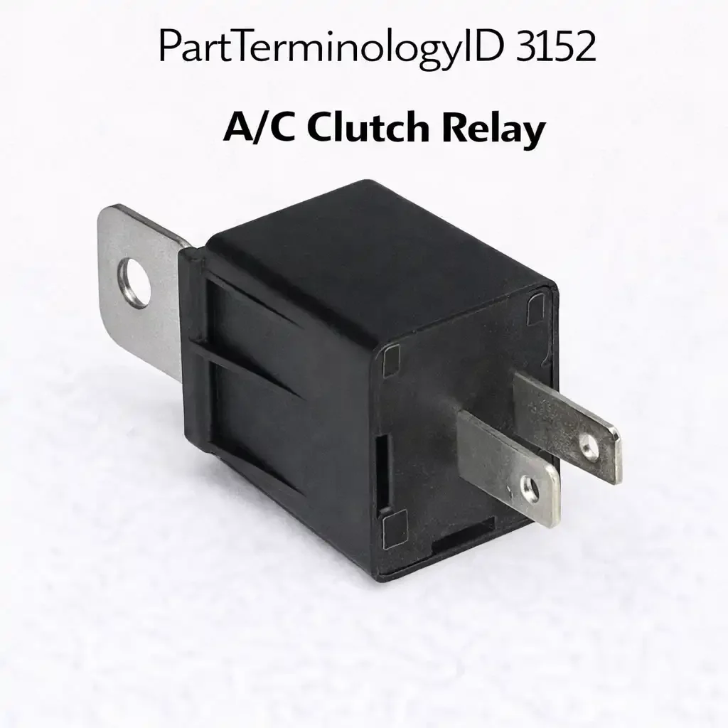
PartTerminologyID 3152, A/C Clutch Relay, is the relay that switches battery voltage to the electromagnetic clutch coil on the A/C compressor, engaging the clutch disc against the pulley face to mechanically connect the compressor to the drive belt when the refrigeration circuit requires compressor operation and releasing it when compressor operation is not needed. That definition covers the clutch engagement switching function correctly and leaves unresolved whether the relay is commanded by the PCM, the HVAC control module, a standalone A/C pressure switch, or a combination of inputs through a logic circuit before the relay coil receives its activation signal, whether the relay switches the clutch coil supply voltage or the clutch coil ground on low-side switched architectures, the contact current rating relative to the clutch coil inrush current which is significantly higher than the coil's steady holding current, whether the relay is a standalone ISO component in the underhood relay center or is integrated into the HVAC control module, and what the PCM does when the relay fails, whether it stores an A/C clutch circuit fault code, disables the A/C request entirely, or activates a failsafe mode that prevents repeated engagement attempts.
For sellers, PartTerminologyID 3152 is the A/C relay PartTerminologyID with the highest buyer population of any in the refrigeration circuit segment, because the A/C clutch relay is the first component any technician reaches for when the compressor does not engage on A/C request. That high buyer volume brings a correspondingly high rate of misdiagnosis-driven orders: the clutch relay receives coil activation voltage from the PCM only after a series of system conditions have been verified, including refrigerant pressure within range, engine coolant temperature below the cutoff threshold, and throttle position below the wide-open throttle cutoff. A relay that receives no coil voltage is not necessarily failed. It may be correctly non-activated because one of the enabling conditions is not met. The listing must describe the A/C clutch relay enabling condition chain explicitly so buyers can verify the relay coil is receiving activation voltage before ordering a replacement relay.
What the A/C Clutch Relay Does
The enabling condition chain and pre-relay diagnosis
The PCM's A/C clutch relay output driver activates only after all enabling conditions are simultaneously satisfied. The refrigerant pressure must be within the operating range defined by the low-pressure and high-pressure switch inputs. The engine coolant temperature must be below the compressor cutoff threshold, typically 118 to 125 degrees Celsius, which prevents compressor loading on an already overheating engine. The throttle position must be below the wide-open throttle cutoff point, which prevents compressor loading during full-power acceleration events. On vehicles with variable displacement compressors the PCM also monitors the A/C system pressure differential to manage compressor displacement rather than cycling the clutch, making the clutch relay less frequently cycled on these architectures.
A buyer who tests the relay by jumping the coil terminals directly and finds the compressor engages and the A/C blows cold has confirmed the relay contact and the clutch coil are functional. The relay is not the fault. The fault is in one of the enabling condition signals that is preventing the PCM from activating the relay coil. Jumping the relay coil to confirm clutch function is the single most valuable pre-order diagnostic step for this PartTerminologyID, and the listing must describe it clearly as the method to distinguish a failed relay from a non-activated relay.
Clutch coil inrush and the contact rating requirement
The A/C clutch electromagnetic coil draws a high initial current at the moment the relay closes, because the coil inductance prevents instantaneous current rise and the initial resistance of the cold coil wire is lower than the warm steady-state resistance. A typical A/C clutch coil draws 5 to 8 amperes in the steady-state holding condition, but the inrush at relay closure may reach 15 to 25 amperes for 10 to 50 milliseconds before the inductance limits current rise to the steady-state value. A relay with a 10-amp contact rating is at risk from repeated inrush events that approach or exceed the contact rating, producing contact erosion that increases contact resistance and reduces the voltage delivered to the clutch coil, reducing clutch engagement force and causing clutch slippage.
Clutch slippage produces a recognizable symptom: the compressor engages briefly and then disengages, the A/C blows cold for a moment and then warms, and the cycle repeats. This intermittent engagement pattern is frequently attributed to low refrigerant charge, a failed compressor, or a cycling pressure switch before the clutch relay contact resistance is measured. A relay contact resistance above 0.05 ohms with the relay closed and energized is indicative of accumulated contact erosion that is reducing clutch engagement voltage below the coil's minimum engagement threshold.
Back-EMF suppression and the clutch coil arc spike
The A/C clutch coil is an inductive load that stores energy in its magnetic field while energized. When the relay opens and de-energizes the clutch coil, the collapsing magnetic field generates a back-EMF voltage spike that can reach 100 to 200 volts momentarily, many times the supply voltage. This spike appears across the relay contact at the moment of opening and arcs across the contact gap, eroding the contact surface with each de-energization event. The arc damage from a single back-EMF spike is small, but the A/C clutch cycles on and off dozens of times per hour during normal air conditioning operation, accumulating arc damage over thousands of cycles during a single hot season.
A suppression diode across the clutch coil clamps the back-EMF spike to a voltage just above the supply voltage, eliminating the arc at the relay contact. Some OEM relay assemblies include a built-in suppression diode. Some rely on a diode built into the compressor clutch coil circuit external to the relay. A replacement relay that lacks a suppression diode for an application where the original included one will experience accelerated contact erosion from the unsuppressed back-EMF arc at each clutch de-energization cycle. The listing must identify whether back-EMF suppression is integrated into the relay or provided externally to allow buyers to confirm the suppression architecture is maintained in the replacement.
Why This Part Generates Returns
Buyers return A/C clutch relays because the relay is not receiving coil activation voltage due to a failed pressure switch or a PCM enabling condition fault, the compressor clutch coil itself is open-circuited and draws no current from a confirmed-good relay, the back-EMF suppression diode is absent in the replacement and the contact erodes rapidly from arc damage, a variable displacement compressor on this vehicle does not cycle the clutch and the relay is never the fault source for an A/C-not-cooling complaint, and the relay coil resistance is outside the PCM driver output tolerance generating a PCM output fault code after the new relay is installed.
Status in New Databases
PIES/PCdb: PartTerminologyID 3152, A/C Clutch Relay
PIES 8.0 / PCdb 2.0: No change.
Top Return Scenarios
Scenario 1: "Enabling condition not met, relay never activated, compressor fault is upstream"
The buyer's A/C does not blow cold. The relay receives no coil voltage. The low-pressure switch is open because the refrigerant charge is low. The PCM correctly withholds relay activation. The buyer replaces the relay. After installation the relay still receives no coil voltage. The enabling condition is still not met.
Prevention language: "Pre-order diagnosis: Measure voltage at the relay coil terminal with A/C requested. If no voltage is present, the PCM is not activating the relay due to an enabling condition fault: low refrigerant pressure, engine overtemperature, wide-open throttle cutoff, or PCM A/C disable. Address the enabling condition before ordering a relay. Jump the relay coil manually to confirm the compressor clutch engages and the contact and coil are functional."
Scenario 2: "Clutch coil open, relay confirmed activating, compressor still does not engage"
The buyer confirms voltage at the relay contact output with the relay activated. The compressor clutch does not engage. The clutch coil has failed open and draws no current. The relay is functional. The compressor clutch coil requires replacement.
Prevention language: "Clutch coil check: Measure resistance across the compressor clutch coil terminals. Normal resistance is 2 to 5 ohms. An open circuit reading indicates a failed clutch coil. A confirmed relay activation with no clutch engagement points to the coil, not the relay."
Scenario 3: "No back-EMF suppression, contact erodes rapidly, intermittent engagement within weeks"
The replacement relay lacks a built-in suppression diode. The original relied on a built-in diode for arc suppression. Each clutch de-energization event arcs across the new relay contact. After one summer season of heavy A/C use, the contact resistance has increased enough to cause intermittent clutch engagement. The buyer returns the relay after a single season of use.
Prevention language: "Back-EMF suppression: [Integrated suppression diode included / No integrated diode, external suppression required]. Verify suppression architecture matches the original. A relay without integrated suppression on a high-cycle A/C application will exhibit accelerated contact erosion from clutch coil back-EMF arc at each de-energization event."
Listing Requirements
PartTerminologyID: 3152
enabling condition chain description with pre-order diagnosis note (mandatory)
contact current rating: holding and inrush (mandatory)
back-EMF suppression: integrated or external (mandatory)
coil resistance within PCM driver tolerance (mandatory)
circuit switched: supply or ground (mandatory)
variable displacement compressor inapplicability note where applicable (mandatory)
clutch coil open circuit diagnosis note (mandatory)
OEM part number cross-reference (mandatory)
Catalog Checklist for ACES/PIES Teams
PartTerminologyID = 3152
require enabling condition chain note (mandatory)
require back-EMF suppression disclosure (mandatory)
require contact inrush rating (mandatory)
require clutch coil diagnosis note (mandatory)
prevent variable displacement compressor misapplication: on these platforms the clutch does not cycle and a clutch relay fault is not the cause of A/C performance complaints
differentiate from A/C Compressor Control Relay (PartTerminologyID 3184): the clutch relay directly engages the electromagnetic clutch; the compressor control relay may manage a broader compressor enable circuit on some architectures; circuit role distinction required
FAQ (Buyer Language)
How do I know if the relay is the problem or something upstream?
Measure voltage at the relay coil terminal with A/C requested. If voltage is present and the compressor does not engage, the relay or clutch coil has failed. If no voltage is present, the PCM is not activating the relay due to an upstream enabling condition fault. Jump the relay coil to confirm the compressor engages before ordering a replacement relay.
Why does my compressor engage briefly then disengage repeatedly?
Possible causes: marginal relay contact resistance reducing clutch engagement voltage, low refrigerant charge causing the cycling pressure switch to open, or a partially shorted clutch coil drawing excess current. Measure relay contact resistance with the relay closed. Above 0.05 ohms indicates contact erosion requiring relay replacement.
Does my variable displacement compressor use a clutch relay?
Variable displacement compressors modulate output without cycling the clutch in most operating conditions. On these platforms the clutch engages at startup and remains engaged, making the relay fault rate very low and the relay an unlikely fault source for A/C performance complaints. Confirm the compressor type before ordering a clutch relay.
Cross-Sell Logic
A/C Compressor Clutch: for buyers confirmed to have a functional relay with a failed clutch coil; the coil is replaceable separately on most compressors without replacing the complete compressor assembly
A/C Low Pressure Switch: the most common upstream enabling condition fault that prevents relay activation; cross-sell with every A/C clutch relay listing with a note about pressure switch diagnosis
A/C Compressor Control Relay (PartTerminologyID 3184): the companion relay on vehicles that separate clutch engagement from broader compressor circuit control
Final Take for PartTerminologyID 3152
A/C Clutch Relay (PartTerminologyID 3152) is the highest-volume A/C relay PartTerminologyID and the one with the most upstream misdiagnosis risk. The enabling condition chain note and the relay coil jump test instruction are the two pre-order diagnostic tools that convert a buyer who would otherwise replace the relay based on symptom alone into a buyer who confirms the relay is actually the fault source before ordering. Back-EMF suppression disclosure and inrush current rating are the two post-installation attributes that determine whether the replacement survives its first season of high-cycle A/C operation.